Hydraulic Actuator Bearing Swage & Proof Load Tool
Objective:
We received a batch of custom actuators that required a bearing to be installed and proof load tested, but we did not have a tool capable of seating the bearing or holding the assembly securely during testing.
Solution:
Design and build a fixture that can be used in a hydraulic press to accurately press the bearing into the actuator rod end while also supporting a gauge setup for proof load testing.
Tools/Skills Used:
Autodesk Inventor, GD & T, Manual Mill, Manual Lathe, Welding, Heat Treating
Approach:
Reviewed the incoming actuator geometry and performance requirements, modeled the fixture in Inventor with appropriate tolerances, machined the components on a mill and lathe, and welded the assembly into a press-compatible fixture.
My Role:
Led the project from design to fabrication, collaborating with the lead hydraulics engineer to validate the concept and ensure the final tool met performance and safety requirements.
Results/Impact:
The finished fixture seated bearings reliably and enabled accurate proof load testing, eliminating the need to outsource the process and saving the company over $10,000.

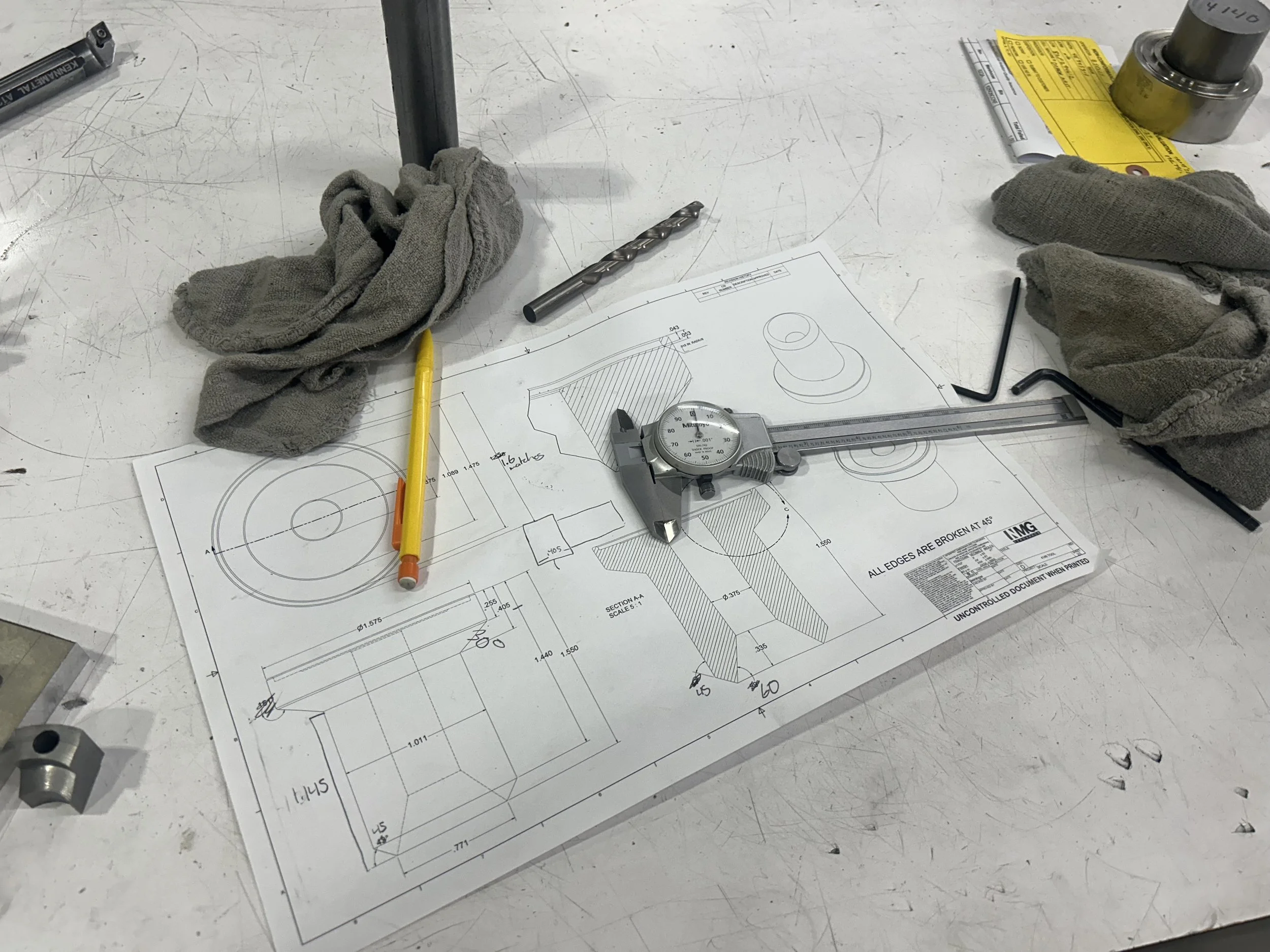
The first step was to examine the actuator itself — measuring the rod end, assessing the bearing fit, and determining the required seating depth. This information guided the geometric requirements of the fixture. I also studied how proof load testing forces would be transferred through the fixture to avoid deformation or slipping during use. Understanding both the dimensional and load-bearing constraints set the foundation for the tool design.
Using Autodesk Inventor, I modeled the fixture with appropriate GD&T callouts to ensure alignment and repeatability. The design incorporated a support block, press alignment surfaces, and a gauge-mounting feature. Multiple iterations were reviewed to ensure manufacturability using the tools and stock materials available on site. Once approved, the prints were taken to the shop for fabrication.
The completed fixture allowed bearings to be pressed in accurately and proof load tested in-house, ensuring every actuator met quality and performance specifications. The tool performed exactly as intended and integrated smoothly into the production workflow. By building the tool internally, the company avoided outsourcing costs and lead time, saving over $10,000. The project demonstrated how hands-on engineering, thoughtful design, and practical fabrication can solve real manufacturing challenges efficiently.

This was another project I was really proud of. This was the first time I really took on a complicated project heads-on, bringing this tool from concept to design to fabrication all by myself. During production, we received a batch of custom hydraulic actuators that required a bearing to be pressed into the rod end and then proof load tested to verify structural integrity. However, we did not have a tool that could both seat the bearing accurately and support the actuator securely during testing. Without the correct fixture, the components could not be assembled to specification, halting progress. This created an immediate need for an in-house solution to avoid costly delays.
The goal was to design and build a fixture that could be placed in a hydraulic press to press the bearing into the actuator while also allowing a gauge to be attached for proof load testing. The fixture needed to be dimensionally precise, rigid enough to withstand load testing forces, and simple for associates to use repeatedly. To ensure safety and repeatability, proper alignment and tolerance control were critical. A custom tool was the most efficient and cost-effective path forward.
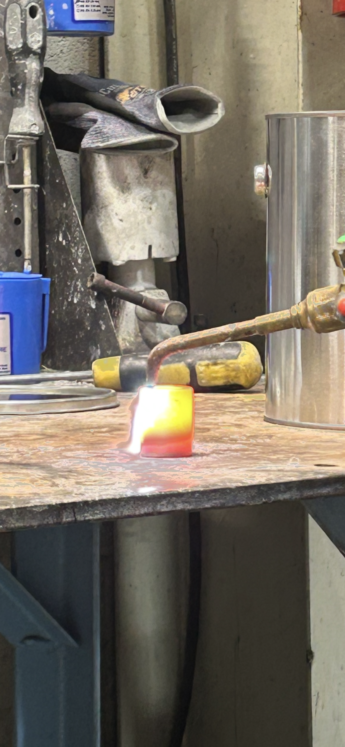
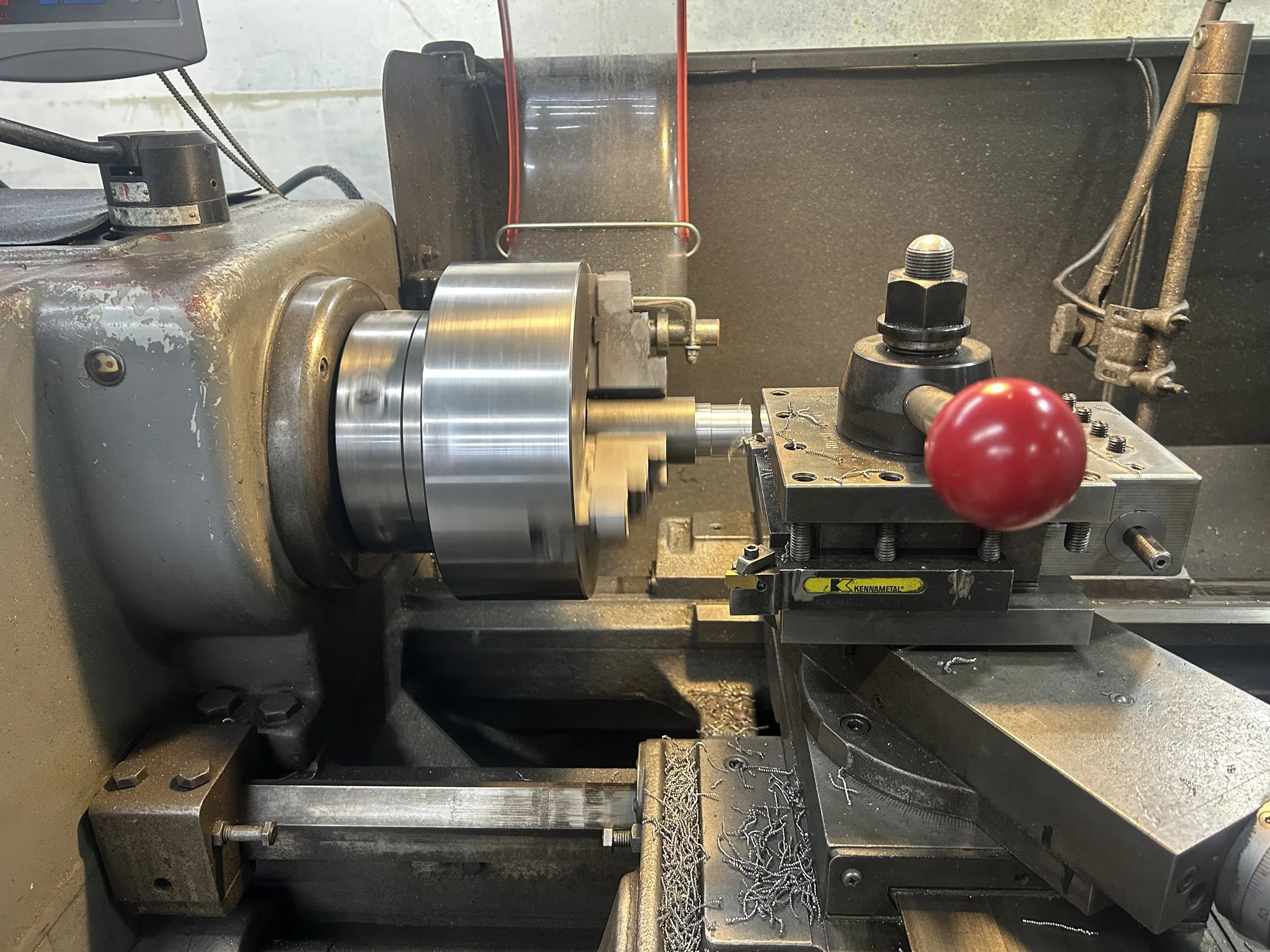
I machined the components on the manual lathe and mill, making sure the alignment faces and diameters matched the toleranced dimensions from the CAD model. After machining, I welded the pieces together, ensuring squareness and structural rigidity so the fixture would withstand proof load forces. In some areas, heat treating was used to strengthen high-impact contact surfaces. The final assembly was then test-fitted and checked before operational use.
Throughout the process, I worked closely with the lead hydraulics engineer to confirm that both the functional and safety requirements were being met. His experience helped validate that the fixture design would support the proof load testing procedure correctly and reliably. This collaboration ensured the final product was not only structurally sound, but also aligned with testing protocols and operator workflow. The teamwork accelerated the build and increased confidence in the final tool.